Resources
Optical Circulator
Optical Circulator Tutorial
Fiber optic communication has brought us a new Internet society. To better support an optical network, a variety of optical components and related technologies are neede. They have contributed to the evolution of optical communication, while improving the functionalities, reliability, and economical efficiency of optical networks. Passive optical components are the foundation stone of optical network systems, and optical circulator is one of them. This tutorial will comprehensively introduce the optical circulator.
What is Optical Circulator?
Optical Circulator is a nonreciprocal device that directs an optical signal from one port to the next, in only one direction at a time. While the direction of the optical signal may be redirected as needed, the optical signal must pass through ports sequentially (i.e. from port 1, to port 2, before traveling to port 3). Additionally, optical circulator can be used to achieve bi-directional transmission over a single fiber. Because of its high isolation of the input and reflected optical powers and its low insertion loss, optical circulator is widely used in advanced communication systems and fiber optic sensor applications.
How does Optical Circulator Work?
Optical circulator operates in a similar way to optical isolator which also uses Faraday rotators, however, its construction is more complex. Its reverse propagating lightwave is directed to a third port for output, instead of being lost. Figure 1(a) shows a three-port optical circulator. An input signal (λ1) at Port 1 exits at Port 2, an input signal (λ2) at Port 2 exits at Port 3, and an input signal (λ3) at Port 3 exits at Port 1. In the same way, in a four-port optical circulator, as shown in Figure 1(b), one could ideally have four inputs and four outputs. In practise, many applications do not need four inputs and four outputs. Therefore, in a four-port circulator, it is common to have three input ports and three output ports. This is done by making Port 1 an input-only port, Port 2 and Port 3 input and output ports, and Port 4 an output-only port.

Figure 1. 3-port Optical Circulator and 4-port Optical Circulator
Types of Optical Circulators
According to the number of ports, optical circulators can be usually classified as three types: 3-port, 4-port and 6-port. In general, 3-port and 4-port circulators are quite common, while the 6-port circulators are less commonly used. No matter which port-type of the optical circulators, optical light is transmitted from any of the port in such circulators can be redirected to any other port.
In addition, optical circulators can also be classified as two types in the market: Polarization Maintaining (PM) and Polarization Insensitive (PI). PM optical circulator is manufactured with polarization maintaining fiber, making them ideal for polarization maintaining applications such as 40Gbps systems or Raman pump applications. They are also used in double-pass amplifiers and in Dispersion Compensation Modules (DCMs). PI optical circulator is a compact, high-performance lightwave component. This component provides high isolation, low insertion loss, low Polarization Dependent Loss (PDL), and high stability and reliability. It is widely used in combination with fiber gratings and other reflective components in Dense Wavelength Division Multiplexing (DWDM) systems, high speed systems and bi-direction communication systems.
Applications of Optical Circulators
Optical circulator supports bi-directional ports and allows a single fiber to be used for both transmission and reception of an optical signal. It is widely used in many applications, such as DWDM networks, polarization mode dispersion, chromatic dispersion compensation, Optical Add-drop Multiplexers (OADMs), optical amplifiers, and fiber optic sensors.
DWDM Networks
Optical circulator can be used to drop an optical channel from a DWDM system using a Fiber Bragg Grating (FBG) (shown in Figure 2). The input DWDM channels are coupled into Port 1 of the device with a FBG device connected to Port 2. The single wavelength reflected from the FBG then reenters the Circulator in Port 2 and is routed accordingly to Port 3. The remaining signals pass through the FBG and exit on the top fiber.

In addition, the optical circulator is also used to separate forward and backward propagating signals with 50 dB of isolation (protection of the input fiber from returning power while employing the rejected light) in DWDM systems. Optic circulator also provides a level of cross-talk (the ratio of the output power produced by the desired input to the output power produced by undesired inputs) of more than 60 dB. This allows a single fiber to effectively transmit a bi-directional signal. (Shown in Figure 3)
.png)
OADM
OADM is based on one FBG and two optical circulators. 4 channels, depicted as 4 colours, impinge onto an FBG via an optical circulator. The FBG is set to one of the channels, here Channel 4, which is reflected back to the circulator where it is directed down and "dropped" out of the system. Since the channel has been dropped, another signal on that channel can be "added" at the same point in the network. Shown in Figure 4)
Figure 4. Optical circulator used in OADM
|
Polarization Mode DispersionSome fiber optic systems experience polarization mode dispersion (PMD), an inherent property of all optical media. PMD is caused by the difference in the propagation velocities of light in the orthogonal principal polarization states of the transmission medium. If the optical pulse contains both polarization components, then the different polarization components in optical circulators will travel at different speeds and arrive at different times, smearing the received optical signal. With optical couplers, optical circulators can correct PMD by rotating the electric and magnetic field of the optical signal. (Shown in Figure 5)
|
 Figure 5. Polarization Mode Dispersion (PMD)
|
Chromatic Dispersion Compensation
Optical circulator compensates for chromatic dispersion by using a chipped FBG (wavelength dependent reflector). A section of optical fiber is treated or doped with a material that changes the refractive index of the fiber, causing wavelength dependent reflections. Chipped FBGs have several gratings displaced throughout a fiber and allow for compensation of chromatic dispersion. (Shown in Figure 6)
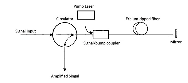
Optical Amplifiers
Optical amplifiers create a direct amplification of a signal without needing to convert it into an electrical signal. Optical circulators feed the input signal into the amplifier, receive the amplified signal, and reroute the signal to an output port. In this application the optical circulator supplies suppressed feedback from the cavity. Figure 7 shows this process.
Location
No.99 Guanlan Avenue
Longhua District, Shenzhen 518110
Guangdong Province, P.R. China
Tel : +86-27-8720-8018
Email: [email protected]
