

As optical networks carry more wavelengths and higher data rates, maintaining sufficient optical power over long fiber spans becomes increasingly difficult.
Fiber attenuation, connectors, splices, splitters and other passive components all reduce signal power. When the received signal falls below the sensitivity limit of the optical receiver, transmission errors may increase or the link may fail completely.
An Erbium-Doped Fiber Amplifier, commonly known as an EDFA, addresses this problem by amplifying optical signals directly in the optical domain. Unlike an electrical repeater, an EDFA does not need to convert the incoming signal into an electrical signal and then back into light.
This makes EDFA technology particularly valuable in:
- Long-haul optical transmission
- Metropolitan-area networks
- DWDM systems
- Data center interconnects
- CATV distribution
- Fiber sensing and laboratory systems
However, an EDFA is not simply a device that makes every optical signal stronger. Its gain, output power, noise figure, operating wavelength and position within the link must all be matched to the network design.
What Is an EDFA Optical Amplifier?
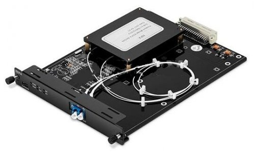
EDFA stands for Erbium-Doped Fiber Amplifier.
It is an optical amplifier that uses a short section of silica fiber doped with erbium ions as the gain medium. When this erbium-doped fiber is energized by a pump laser, it can transfer energy to optical signals within specific wavelength bands.
EDFAs are most commonly used in:
- The C-band, approximately 1530–1565 nm
- The L-band, approximately 1565–1625 nm
The exact operating range depends on the amplifier design.
Because many telecommunications and DWDM systems operate near 1550 nm, where standard single-mode fiber has relatively low attenuation, EDFA technology has become an important part of modern optical transmission systems.
How Does an EDFA Work?
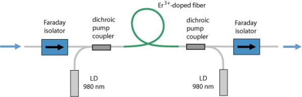
An EDFA typically contains the following components:
- Pump laser
- Wavelength-division multiplexer
- Erbium-doped fiber
- Optical isolators
- Optical couplers and monitoring photodiodes
- Control and protection circuitry
The amplification process can be summarized in four stages.
1. Pumping the Erbium Ions
A pump laser injects optical energy into the erbium-doped fiber.
Common pump wavelengths are:
- 980 nm
- 1480 nm
The pump energy raises erbium ions into an excited energy state.
2. Input Signal Enters the Gain Fiber
The incoming optical signal passes through the erbium-doped fiber.
When the signal wavelength falls within the amplifier’s operating band, its photons interact with the excited erbium ions.
3. Stimulated Emission Occurs
The interaction causes the excited erbium ions to release additional photons.
These newly generated photons have the same frequency, phase and propagation direction as the incoming signal photons. The optical signal therefore becomes stronger as it travels through the doped fiber.
4. The Amplified Signal Leaves the EDFA
The amplified signal exits the device and continues through the optical network.
Optical isolators are commonly used to reduce unwanted reflections and prevent backward-propagating light from destabilizing the amplifier.
980 nm vs. 1480 nm Pumping
Both 980 nm and 1480 nm pump lasers can be used in EDFA designs, but they have different characteristics.
980 nm Pumping
A 980 nm pump is commonly selected when low noise is important.
It is frequently used in:
- Optical pre-amplifiers
- Low-noise C-band EDFAs
- Receiver-side amplification
- DWDM systems with strict OSNR requirements
1480 nm Pumping
A 1480 nm pump can provide high conversion efficiency and may support bidirectional or high-output-power designs.
It is frequently used in:
- Booster amplifiers
- High-power EDFAs
- L-band amplifiers
- Systems requiring efficient optical power generation
Some high-performance EDFAs use multiple pump lasers or combine 980 nm and 1480 nm pumping to balance gain, noise and output-power requirements.
Main Types of EDFA Optical Amplifiers
The same EDFA technology can perform different functions depending on where the amplifier is installed in the optical link.
1. Booster Amplifier
A booster amplifier is installed near the optical transmitter.
Its main purpose is to increase launch power before the signal enters a long fiber span or a high-loss passive network.
Typical applications include:
- Increasing transmitter launch power
- Compensating for splitter or multiplexer loss
- CATV signal distribution
- DWDM transmitter-side amplification
- Long-distance backbone transmission
A booster amplifier normally emphasizes:
- High saturated output power
- Good output-power stability
- Multi-channel amplification
- Protection against excessive input or reflected power
Noise figure is still important, but it is usually less critical than in a receiver-side pre-amplifier because the input signal is already relatively strong.
2. In-Line Amplifier
An in-line EDFA is installed between two fiber spans.
Its purpose is to compensate for attenuation accumulated in the preceding span so that the signal can continue through the next section of fiber.
In-line amplifiers are widely used in:
- Long-haul transmission
- Metro optical networks
- Multi-span DWDM systems
- Submarine and terrestrial optical systems
- Extended data center interconnects
An in-line amplifier must be selected carefully because each amplification stage adds amplified spontaneous emission noise.
When several EDFAs are cascaded, the system designer must evaluate:
- Optical signal-to-noise ratio
- Gain flatness
- Channel power balance
- Fiber nonlinearity
- Chromatic dispersion
- Total link-loss budget
3. Pre-Amplifier
A pre-amplifier is installed close to the optical receiver.
Its purpose is to increase a weak incoming signal before detection.
Pre-amplifier designs generally prioritize:
- Low noise figure
- High sensitivity to weak input signals
- Stable gain
- Low polarization-dependent gain
- Good optical signal-to-noise performance
Pre-amplifiers are commonly used in:
- Long-reach optical receivers
- DWDM terminal equipment
- Low-power sensing systems
- Laboratory detection systems
- Links approaching the receiver sensitivity limit
Because the received signal is already weak, excessive amplifier noise can significantly affect system performance. Low-noise design is therefore particularly important.
Booster vs. In-Line vs. Pre-Amplifier
| EDFA Type | Installation Position | Primary Function | Most Important Characteristics |
|---|---|---|---|
| Booster amplifier | After the transmitter | Increase launch power | High output power and stable power control |
| In-line amplifier | Between fiber spans | Compensate for span loss | Gain flatness, output power and OSNR management |
| Pre-amplifier | Before the receiver | Improve weak-signal detection | Low noise figure and high sensitivity |
Some systems use all three types in the same optical route.
Key EDFA Specifications
Understanding EDFA specifications is essential when selecting an amplifier.
Gain
Gain describes how much the EDFA increases the optical signal power.
It is expressed in decibels:
Gain = Output power − Input power
For example, if the input signal is −20 dBm and the output signal is +5 dBm, the amplifier gain is approximately 25 dB.
Typical EDFA gain may range from approximately 15 to 35 dB, although specialized products may provide values outside this range.
The maximum specified gain is not always available at every input-power level. Gain compression may occur as the amplifier approaches its saturated output power.
Saturated Output Power
Saturated output power is the maximum practical output level that the amplifier can deliver while maintaining controlled performance.
Common EDFA output-power classes include:
- +13 dBm
- +17 dBm
- +20 dBm
- +23 dBm
- Higher-power customized designs
CATV and high-split-count distribution systems may require substantially higher total output power.
The required output power should be calculated from the complete link-loss budget rather than selected solely on the principle that higher power is better.
Excessive launch power can cause:
- Receiver overload
- Fiber nonlinearities
- Increased crosstalk
- Component damage
- Reduced system stability
Noise Figure
Noise figure describes the degradation of the optical signal-to-noise ratio introduced by the amplifier.
A lower noise figure is generally preferable.
Depending on the amplifier design and operating condition, a practical EDFA may have a noise figure of approximately 4.5–6 dB. Low-noise pre-amplifiers may be optimized for lower values, while high-power amplifiers may prioritize output power instead.
Noise figure should always be evaluated at the intended:
- Input-power range
- Gain setting
- Wavelength
- Channel loading condition
Gain Flatness
A DWDM EDFA may amplify many wavelength channels simultaneously.
Without gain-flattening control, some wavelengths may receive more gain than others. After several cascaded amplifier stages, this difference can become significant.
Gain flatness describes the variation in gain across the operating wavelength range.
A gain-flattening filter may be integrated into the EDFA to help maintain consistent channel power across the C-band or L-band.
This is particularly important in:
- Multi-channel DWDM links
- Cascaded amplifier systems
- Long-haul transmission
- Networks with frequent channel additions and removals
Input-Power Range
Every EDFA is designed to operate within a specified input-power range.
If the input is too weak:
- The output may contain a high proportion of ASE noise.
- OSNR may become unacceptable.
- The amplifier may not achieve useful signal quality.
If the input is too strong:
- Gain compression may occur.
- The amplifier may reach output saturation.
- Individual channel powers may become unbalanced.
- Nonlinear effects may increase.
For multi-channel systems, confirm whether the specified input power refers to:
- Total composite input power
- Input power per channel
Confusing these two values can result in incorrect amplifier selection.
Polarization-Dependent Gain
Polarization-dependent gain describes how amplifier gain changes with the state of polarization of the input signal.
A low value is desirable because normal transmission fiber can cause the input polarization state to vary over time.
This specification is particularly relevant to:
- Coherent transmission
- Polarization-sensitive optical systems
- Test and measurement
- Precision laboratory applications
Return Loss and Isolation
Optical reflections can affect amplifier stability and system performance.
Internal isolators help prevent reflected signals from propagating back into the gain stage or pump laser.
The amplifier datasheet may specify:
- Input return loss
- Output return loss
- Input isolation
- Output isolation
High-quality connectors and clean end faces remain necessary even when the EDFA includes optical isolation.
Amplified Spontaneous Emission
An EDFA does not amplify only the intended signal.
Excited erbium ions can also emit photons spontaneously. These photons are amplified as they travel through the gain fiber, producing Amplified Spontaneous Emission, or ASE.
ASE appears as broadband optical noise around the amplifier’s operating wavelengths.
Its effects may include:
- Reduced OSNR
- Receiver-performance degradation
- Accumulated noise in cascaded amplifiers
- Higher total output power without useful signal power
- Reduced transmission reach
For this reason, amplifier design cannot be based only on gain and output power. ASE and OSNR must also be considered.
EDFA Control Modes
Depending on the amplifier design, an EDFA may support several operating modes.
Automatic Gain Control
Automatic Gain Control maintains a target gain as input power changes.
This mode can be useful when stable amplification is required across varying signal conditions.
Automatic Power Control
Automatic Power Control maintains a target total output power.
It is commonly used in booster amplifiers and systems where launch power must remain stable.
Automatic Current Control
Automatic Current Control maintains a specified pump-laser drive current.
This mode is useful for laboratory control and certain fixed operating conditions, but output power may vary if the input signal changes.
Not every EDFA supports all three modes. Available modes should be confirmed in the product specification.
Advantages of EDFA Optical Amplifiers
Direct Optical Amplification
An EDFA amplifies optical signals without optical-electrical-optical conversion.
This reduces the need for wavelength-specific electrical regeneration at every span.
Simultaneous Multi-Channel Amplification
A properly designed EDFA can amplify multiple DWDM channels at the same time.
This makes it more scalable than using a separate electrical repeater for every wavelength.
High Optical Gain
EDFAs can compensate for substantial fiber and component loss within one amplification stage.
Low Noise
Low-noise EDFA designs provide suitable performance for receiver-side and long-haul applications.
Transparency to Data Format
An EDFA responds primarily to optical wavelength and power rather than the encoded data format.
It can therefore amplify compatible signals carrying different:
- Data rates
- Modulation formats
- Network protocols
However, this does not mean the amplifier is completely independent of system design. High-power coherent and dense-channel systems still require careful nonlinear and OSNR analysis.
Compatibility With DWDM Systems
The EDFA operating range overlaps the C-band and L-band regions commonly used by DWDM networks.
Gain-flattened designs can support simultaneous amplification of many channels.
Limitations of EDFA Technology
EDFA technology provides significant benefits, but it also has important limitations.
Limited Wavelength Range
Standard EDFAs are mainly designed for C-band or L-band signals.
They are not the normal choice for:
- 850 nm multimode systems
- 1310 nm O-band networks
- Visible-light applications
- Many specialty wavelengths
Other amplifier technologies may be required for these bands.
Amplification of Noise
An EDFA amplifies existing signal noise and also introduces ASE.
It does not distinguish between a clean signal and a distorted signal.
No Signal Reshaping or Retiming
An EDFA performs optical amplification, but it does not:
- Restore distorted pulse shape
- Correct timing errors
- Recover clock information
- Remove accumulated noise
- Correct chromatic dispersion
This distinguishes optical amplification from 2R or 3R regeneration.
A long optical route may still require electrical regeneration when OSNR, dispersion or waveform quality can no longer meet the receiver requirements.
Potential Fiber Nonlinearities
Excessive optical launch power can cause nonlinear effects such as:
- Self-phase modulation
- Cross-phase modulation
- Four-wave mixing
- Stimulated Brillouin scattering
- Stimulated Raman scattering
The acceptable power level depends on fiber type, channel spacing, transmission distance and modulation format.
Channel-Power Imbalance
In multi-channel systems, non-flat gain or changing channel loading can cause unequal output power among wavelengths.
Gain-flattening filters and dynamic control may be required.
EDFA vs. Other Optical Amplifiers
EDFA is one of several optical-amplifier technologies.
| Amplifier Type | Common Wavelength Region | Main Advantages | Typical Applications |
|---|---|---|---|
| EDFA | C-band and L-band | High gain, low noise and strong DWDM compatibility | Long-haul, metro, CATV and DCI |
| Semiconductor optical amplifier | Device-dependent | Compact size and potential integration | Photonic circuits, switching and short systems |
| Raman amplifier | Broad, pump-dependent range | Distributed gain and improved effective noise performance | Long-haul and ultra-long-haul systems |
| Ytterbium-doped fiber amplifier | Around 1 μm | High output power | Fiber lasers and industrial systems |
| Thulium-doped fiber amplifier | Around 2 μm | Amplification in specialty wavelength bands | Research, sensing and emerging communications |
EDFA vs. Raman Amplifier
An EDFA uses a dedicated erbium-doped fiber as its gain medium.
A Raman amplifier uses stimulated Raman scattering, often within the transmission fiber itself.
EDFA Advantages
- Mature technology
- Compact amplifier modules
- High gain
- Relatively straightforward deployment
- Broad C-band and L-band product availability
Raman Amplifier Advantages
- Distributed amplification along the transmission span
- Flexible gain wavelength through pump selection
- Potential improvement in effective noise performance
- Extended transmission reach
Hybrid EDFA–Raman systems combine both technologies to achieve high gain, improved OSNR and longer transmission spans.
They are more complex and require careful pump-power and safety management.
EDFA Applications
DWDM Networks
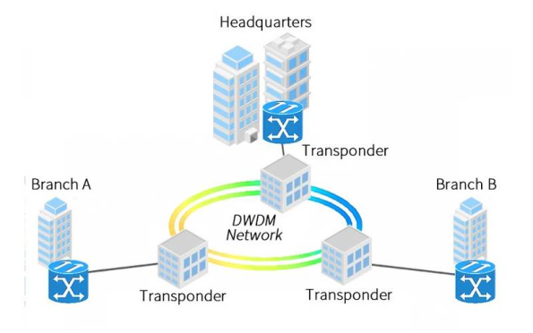
EDFA is widely used in DWDM systems because one amplifier can amplify multiple wavelength channels simultaneously.
Typical positions include:
- After the DWDM multiplexer
- Between long fiber spans
- Before the DWDM demultiplexer
- Within reconfigurable optical add-drop networks
Long-Haul Telecommunications
Long-distance backbone networks use optical amplifiers to compensate for span loss and reduce the number of electrical regeneration sites.
The complete system must still account for:
- ASE accumulation
- Fiber dispersion
- Nonlinear effects
- Channel-power balance
- Coherent receiver performance
Metropolitan-Area Networks
Metro networks may use EDFAs to extend links between central offices, data centers and access nodes.
Compact 1U rack-mounted or modular EDFAs are common in these applications.
Data Center Interconnects
When two data centers are separated by a distance beyond the supported reach of the installed transceivers, an EDFA may form part of the optical transport design.
EDFA suitability depends on:
- Optical wavelength
- Modulation format
- Transceiver launch power
- Receiver sensitivity
- Link-loss budget
- Available OSNR margin
An EDFA should not be inserted into a direct-detect or coherent link without verifying module compatibility.
CATV Networks
CATV systems use high-output-power EDFAs to distribute optical signals to multiple subscribers.
These designs often emphasize:
- High saturated output power
- Multiple output ports
- Stable automatic power control
- Low noise
- Good carrier-to-noise performance
Passive Optical Networks
Specialized amplifiers may be used in extended-reach or high-split-count PON systems.
However, standard PON networks operate across several wavelengths, including wavelengths outside the normal EDFA gain band. The complete bidirectional wavelength plan must therefore be evaluated before amplification is introduced.
Fiber Sensing and Laboratory Systems
EDFAs are also used in:
- Fiber sensing
- Coherent experiments
- Optical test benches
- Spectroscopy
- Laser systems
- Component characterization
- Low-power signal detection
Laboratory applications may require additional features such as manual pump-current control, polarization-maintaining fiber, narrowband filtering or external monitoring interfaces.
How to Select an EDFA
Before selecting an EDFA optical amplifier, confirm the following parameters.
| Selection Factor | Questions to Confirm |
|---|---|
| Amplifier position | Is it a booster, in-line amplifier or pre-amplifier? |
| Operating wavelength | Is C-band, L-band or a customized range required? |
| Input power | What is the total and per-channel input-power range? |
| Required gain | How much link loss must be compensated? |
| Output power | What launch power can the next fiber span and receiver tolerate? |
| Noise figure | What OSNR margin is required? |
| Channel count | Is the system single-channel or DWDM? |
| Gain flatness | Must all wavelength channels maintain similar output power? |
| Control mode | Is AGC, APC or ACC required? |
| Fiber type | Is standard single-mode or polarization-maintaining fiber required? |
| Connector type | LC/UPC, LC/APC, SC/UPC or another interface? |
| Monitoring | Are input/output power monitoring and alarms required? |
| Form factor | Benchtop, module, 1U rack-mount or network-managed chassis? |
| Power supply | AC, DC or redundant input? |
| Management interface | Local display, RS-232, Ethernet, SNMP or web management? |
Basic EDFA Link-Budget Example
Consider a C-band link with:
- Transmitter output: 0 dBm
- Fiber loss: 18 dB
- Connector and splice loss: 2 dB
- Receiver sensitivity: −18 dBm
Without amplification:
Received power = 0 − 18 − 2 = −20 dBm
The signal is 2 dB below the receiver sensitivity.
An EDFA providing approximately 10 dB of usable gain could raise the received power, but this does not mean a 10 dB amplifier should automatically be selected.
The design must also consider:
- Amplifier noise figure
- Required system margin
- Receiver overload limit
- Output saturation
- ASE
- Future component aging
- Channel loading
- Nonlinear-power limits
A practical design normally includes additional engineering margin.
Common EDFA Selection Mistakes
Selecting Only by Maximum Gain
High gain is not always useful if the EDFA reaches output saturation or introduces excessive ASE.
Ignoring Total vs. Per-Channel Power
In a DWDM system, a total input of 0 dBm across 40 channels corresponds to much lower power per channel.
Both values must be understood.
Using an EDFA at the Wrong Wavelength
A standard C-band EDFA will not amplify an 850 nm or 1310 nm signal effectively.
Overlooking Receiver Overload
An amplifier may increase the signal above the maximum allowable receiver input.
An optical attenuator may be required in some configurations.
Ignoring Connector Reflections
Poor return loss and dirty connectors can destabilize the link or degrade performance.
Assuming Amplification Repairs a Bad Signal
EDFA increases optical power but does not correct dispersion, timing errors or a poor extinction ratio.
Cascading Too Many Amplifiers Without OSNR Analysis
Every stage introduces ASE. A link may have sufficient power but still fail because its OSNR is too low.
Frequently Asked Questions
Does an EDFA increase network speed?
No.
An EDFA increases optical signal power and can extend transmission distance. It does not change the Ethernet data rate or make light propagate faster.
Can an EDFA amplify multiple wavelengths?
Yes.
A gain-flattened C-band or L-band EDFA can amplify multiple compatible DWDM channels simultaneously.
Can an EDFA amplify 1310 nm signals?
A conventional erbium-doped amplifier is not designed for the 1310 nm O-band. Semiconductor or Raman amplification may be considered depending on the application.
Does an EDFA work with any transceiver?
No.
The transceiver wavelength, launch power, receiver range, modulation format and optical budget must be compatible with the amplifier.
What is the difference between gain and output power?
Gain describes how much the input signal is increased.
Output power is the absolute optical power leaving the amplifier. An EDFA may provide high gain for a weak signal but still be limited by its maximum saturated output power.
Is higher EDFA output power always better?
No.
Excessive power can overload receivers and increase nonlinear effects. Output power should match the link design.
Why does an EDFA need a low noise figure?
The amplifier introduces ASE and reduces OSNR. A lower noise figure helps preserve signal quality, especially when amplifying weak signals or cascading multiple amplifiers.
Can an EDFA replace an optical repeater?
It can reduce the number of electrical repeaters required, but it cannot replace regeneration in every system.
A repeater or regenerator may reshape, retime and retransmit the signal, while an EDFA primarily increases optical power.
Conclusion
EDFA optical amplifiers are essential components in many C-band and L-band optical networks. By amplifying signals directly in the optical domain, they can compensate for fiber and component loss without requiring wavelength-by-wavelength electrical conversion.
Booster amplifiers increase transmitter launch power, in-line amplifiers compensate for intermediate span loss, and pre-amplifiers improve weak-signal reception. Selecting the correct type requires careful consideration of gain, output power, noise figure, wavelength range, gain flatness and total link budget.
An EDFA can extend transmission reach, but it does not repair signal distortion or eliminate accumulated noise. ASE, OSNR, receiver overload and fiber nonlinearities must all be considered in a professional network design.
Sunma supplies configurable C-band and L-band EDFA optical amplifiers for telecommunications, DWDM, CATV, data center interconnect and laboratory applications. Available configurations may include booster, in-line and pre-amplifier designs with customized gain, output power, connector type, control mode and monitoring interface.
