

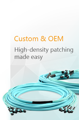
As data centers and enterprise networks add more switches, servers, and high-speed optical links, cable density can become a major operational challenge. Running individual duplex fiber cables for every connection consumes valuable rack space, increases cable congestion, and makes future changes more difficult.
An MPO-12 breakout cable provides a practical way to transition between a high-density multifiber interface and multiple duplex or simplex fiber connections. By consolidating multiple fibers into a single MPO connector at one end and separating them into LC connectors at the other, it can simplify installation while supporting flexible equipment connectivity.
However, an MPO-12 breakout cable is not a universal solution for every optical network. Its suitability depends on the transceiver interface, fiber type, polarity, connector gender, lane assignment, insertion-loss budget, and required breakout configuration.
This guide explains how MPO-12 breakout cables work, where they are commonly used, and what should be checked before deployment.
What Is an MPO-12 Breakout Cable?
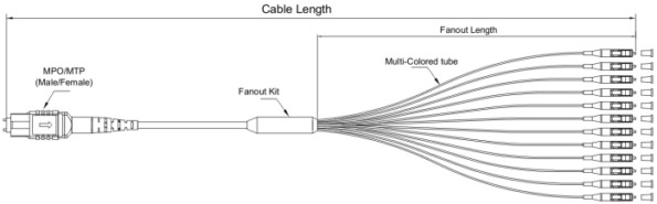
An MPO-12 breakout cable, also known as an MPO-12 fan-out cable or MPO-to-LC harness cable, is a preterminated fiber assembly with one 12-fiber MPO connector on one end and multiple LC connectors on the other.
Depending on the application, a 12-fiber MPO interface may break out into:
- Six LC duplex connectors, using all 12 fibers
- Four LC duplex connectors, using eight fibers
- Twelve LC simplex connectors
- Other application-specific LC arrangements
A six-duplex-LC configuration provides six independent duplex fiber links. A four-duplex-LC configuration is commonly associated with four-lane parallel-optics applications, where eight of the twelve fiber positions carry traffic and the center four positions may remain unused.
Corning, for example, describes 12-fiber harness assemblies with either four or six LC duplex connectors, demonstrating that the correct breakout structure depends on the intended optical architecture.
How Does an MPO-12 Breakout Cable Work?
The MPO connector aligns multiple fibers within a single compact ferrule. Inside the breakout assembly, the individual fibers are separated and routed into smaller cable legs terminated with LC connectors.
The breakout cable does not electronically convert one data rate into another. It is a passive optical assembly that maps individual optical lanes from the MPO interface to the corresponding LC interfaces.
For example, a compatible 40GBASE-SR4 transceiver uses four transmit lanes and four receive lanes through an MPO-12 interface. When the switch and transceiver support breakout operation, an MPO-to-LC assembly can route these lanes to four separate 10GBASE-SR interfaces. Cisco describes this architecture as a 12-fiber parallel-to-duplex breakout connection between one 40GBASE-SR4 module and four 10G optical interfaces.
The network equipment must also be configured to support the required breakout mode. A cable alone cannot cause a 40G port to operate as four independent 10G ports.
Key Benefits of MPO-12 Breakout Cables
Higher Connection Density
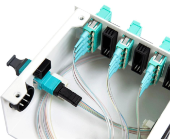
A single MPO connector can terminate multiple fibers in approximately the space required by one multifiber interface. This reduces the number of connectors required on the trunk side and helps increase connection density in patch panels, cassettes, and fiber enclosures.
The benefit becomes particularly noticeable in data centers where hundreds or thousands of duplex links must be routed between equipment rows.
Faster Installation
MPO-12 breakout cables are normally factory terminated and tested. This eliminates much of the field termination and splicing required with individual fiber runs.
Installers can connect the MPO end to a trunk, cassette, patch panel, or compatible transceiver and route the labeled LC legs to their respective ports. This can reduce installation time and lower the risk of inconsistent field terminations.
Simplified Cable Routing
Replacing multiple independent duplex cables with one multifiber assembly can reduce cable congestion in racks, trays, and pathways.
More organized cable routing may also make equipment access, airflow management, and future moves, additions, or changes easier. The actual benefit depends on correct cable-length planning and proper management of the breakout legs.
Flexible Port Breakout
A breakout assembly can allow one high-speed parallel interface to connect to several lower-speed interfaces when the transceivers and network equipment support that mode.
Common examples include:
- 40G to four 10G links
- 100G to four 25G links
- MPO trunks transitioning to multiple duplex LC ports
- High-density patch-panel connections to individual equipment ports
The exact breakout capability must be verified against the switch, line card, transceiver, and operating-system documentation.
Factory-Controlled Performance
Because the cable is preterminated, its connector geometry, polarity, end-face quality, and insertion loss can be tested during manufacturing.
This does not mean that the assembly has no optical loss. Every mated connector pair contributes insertion loss, and the complete channel must remain within the optical power budget specified for the transceivers.
Common Applications
Data Center Structured Cabling
MPO-12 breakout cables are frequently used between high-density trunk cabling and LC-based switches, servers, storage equipment, or patch panels.
A structured cabling system may use MPO trunks between equipment areas, with cassettes or breakout harnesses providing LC connectivity near the active equipment. This approach supports modular deployment and can simplify future reconfiguration.
Parallel-Optics Breakout Connections
Parallel-optics transceivers transmit data across several separate fiber lanes. MPO interfaces provide a compact way to present these lanes at the transceiver.
For compatible 40G applications, a single MPO-12 interface may be divided into four duplex LC channels for four independent 10G links. Cisco lists MPO-12 as the connector interface for several 40GBASE-SR4 modules and documents their use in four-by-10G breakout applications.
Similar principles may apply to other data rates, but the lane count and connector interface must be checked for the specific transceiver. Newer 400G and 800G systems may use MPO-12, MPO-16, dual-row MPO, SN, MDC, CS, or other interfaces depending on the optical specification.
Switch-to-Server Connectivity
Breakout cables can be used to connect a higher-speed switch port to several lower-speed server or access-switch ports.
This arrangement can improve utilization of high-density switch ports, but only when the switch supports port breakout and the selected transceivers are interoperable at both ends.
Telecommunications and Enterprise Networks
Telecommunications rooms and enterprise network facilities may use MPO-to-LC assemblies to connect multifiber backbone cabling to LC-based equipment.
The preterminated design is useful where installation time, rack density, repeatable performance, and simplified network expansion are important.
Testing and Laboratory Systems
MPO breakout cables are also used to access individual fibers in multifiber components during testing, measurement, research, and production.
The LC legs allow conventional optical test equipment to measure the loss, continuity, or power level of individual fibers within an MPO assembly.
MPO-12 Breakout Cable vs. Individual LC Duplex Cables
It is not technically accurate to describe MPO-12 as universally superior to LC. The two connector types serve different functions, and a breakout cable combines them within the same assembly.
| Consideration | MPO-12 Breakout Cable | Individual LC Duplex Cables |
|---|---|---|
| Trunk-side density | Higher | Lower |
| Installation | Preterminated multifiber connection | Each duplex cable installed separately |
| Cable management | Fewer trunk cables | More individual cables |
| Port flexibility | Depends on fixed breakout mapping | Individual links can be changed separately |
| Repairability | Damage may affect a complete harness | One duplex cable can be replaced individually |
| Planning requirements | Polarity and lane mapping are critical | Generally simpler to understand |
| Best suited for | High-density and structured cabling | Small deployments and independent links |
MPO-12 breakout cables are usually more advantageous when connection density and installation speed are priorities. Individual LC duplex cables may remain more practical for small deployments, frequently changing connections, or systems where each link must be independently replaced.
Critical Specifications to Check Before Ordering
1. Fiber Type
The cable fiber must match the transceivers and installed cabling system.
Common options include:
- OS2 single-mode fiber
- OM3 multimode fiber
- OM4 multimode fiber
- OM5 multimode fiber
Single-mode and multimode assemblies are not interchangeable. Connector polish also commonly differs: multimode MPO connectors generally use UPC end faces, while single-mode MPO connections commonly use angled APC end faces.
2. MPO Connector Gender
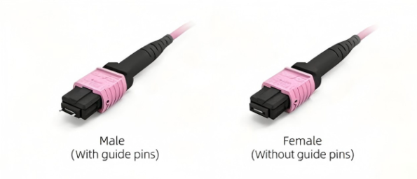
MPO connectors are available as:
- Male, with alignment pins
- Female, without alignment pins
Two pinned MPO connectors should not be mated directly, and two unpinned connectors cannot achieve the required mechanical alignment without the correct mating arrangement.
Active equipment commonly has a pinned MPO interface, meaning the cable connecting directly to it will typically require an unpinned connector. This must still be verified against the specific transceiver.
3. Polarity
Polarity ensures that each transmitter at one end connects to the appropriate receiver at the other end.
MPO systems may use Method A, Method B, Method C, or application-specific fiber mapping. Selecting the wrong polarity can cause link failure even when the connectors physically mate.
Because preterminated MPO assemblies are often built to order, polarity should be confirmed during the design stage rather than after installation.
4. Breakout Configuration
Confirm whether the assembly requires:
- MPO-12 to 4 LC duplex
- MPO-12 to 6 LC duplex
- MPO-12 to 12 LC simplex
- Equal-length or staggered breakout legs
- Standard or custom channel labeling
The correct option depends on the number of active fibers and the intended equipment ports.
5. Connector Polish
Typical combinations include:
- Multimode MPO/UPC to LC/UPC
- Single-mode MPO/APC to LC/UPC
- Other application-specific combinations
UPC and APC MPO interfaces must not be directly mated because their ferrule geometries differ.
6. Insertion Loss
Review the maximum insertion loss for both the MPO and LC ends rather than relying only on a typical value.
The total channel loss may include:
- MPO connector pairs
- LC connector pairs
- Adapters
- Cassettes
- Splices
- Fiber attenuation
- Engineering margin
Low-loss or ultra-low-loss MPO assemblies may be necessary in channels containing multiple mated connections.
7. Cable Length and Breakout-Leg Length
The main cable length should match the planned rack or pathway route without creating excessive slack.
The breakout legs must also be long enough to reach the equipment ports while maintaining the required bend radius. Staggered legs may improve routing when equipment ports are arranged vertically or across multiple line cards.
8. Cable Jacket and Environment
Indoor, plenum, riser, LSZH, outdoor, armored, and industrial cable constructions have different environmental and regulatory characteristics.
A standard indoor MPO breakout cable should not automatically be described as suitable for outdoor use. The cable jacket, moisture resistance, temperature rating, flame rating, tensile strength, and installation method must match the deployment environment.
Common Deployment Mistakes
Assuming Every MPO-12 Cable Has the Same Fiber Mapping
Two MPO-12 assemblies may look identical while using different polarity methods, connector genders, or active fiber positions. Product identification should therefore include more than fiber count and connector type.
Treating the Cable as a Data-Rate Converter
A passive MPO-to-LC cable does not convert 40G into four 10G links by itself. The switch port, operating system, and optical modules must support the required breakout mode.
Ignoring Unused Fibers
Some SR4 applications use only eight fibers in a 12-fiber connector, leaving four positions unused. This is normal for those architectures, but it can reduce fiber-utilization efficiency compared with a native Base-8 design. Fluke Networks notes that 12-fiber MPO connectors can be used for eight-fiber applications with four middle fiber positions unused.
Overlooking Cleaning and Inspection
Contamination on an MPO ferrule can affect several fibers at once. Both MPO and LC end faces should be inspected and cleaned using tools intended for the relevant connector type before mating.
Exceeding the Optical Loss Budget
Additional adapters, cassettes, and patching points can make the network easier to manage but also add insertion loss. The complete link should be calculated and tested against the transceiver’s permitted loss budget.
Are MPO-12 Breakout Cables Future-Proof?
MPO-12 is a mature and widely deployed interface, and it can support a range of structured cabling and breakout applications. It can also help organizations reuse existing multifiber trunks during some network migrations.
However, no single connector architecture is automatically future-proof.
A network’s upgrade capability depends on:
- Installed fiber type
- Base-8 or Base-12 architecture
- MPO polarity
- Connector gender
- Optical loss budget
- Transceiver interface
- Lane count
- Planned migration speeds
- Availability of compatible cassettes and conversion modules
Some newer high-speed applications continue to use MPO-12, while others use MPO-16, dual-row MPO, LC, or very-small-form-factor connectors. A genuinely future-ready cabling design should therefore be based on a defined migration roadmap rather than on the MPO-12 connector alone.
Conclusion
MPO-12 breakout cables provide an effective transition between high-density multifiber cabling and LC-based equipment interfaces. They can reduce trunk-side cable congestion, shorten installation time, and support flexible port breakout when used with compatible network hardware.
Their performance and reliability depend on correct specification. Fiber type, MPO gender, polarity, breakout mapping, connector polish, insertion loss, cable construction, and equipment compatibility must all be confirmed before ordering.
For high-density data centers, telecommunications facilities, enterprise networks, and optical test systems, a properly designed MPO-12 breakout assembly can be an important part of a scalable fiber infrastructure. The key is not simply choosing an MPO-12 cable, but choosing the correct MPO-12 configuration for the complete optical link.
